Plate cutting from drawing to shaped parts
Cutting is the value-added step most plate orders pass through: full sheets in, finished parts out, with nesting, bevels and inspection along the way. This piece walks the flow — from the moment your drawing arrives to the packed, marked parts leaving the shed.
Step one: what a good drawing contains
A DXF/DWG with closed contours and dimensions is ideal. A marked-up sketch also works if it states three things without asking: grade, thickness, quantity. Add mating dimensions where parts fit together, and declare the extras early — bevel type, cut-face finish, diagonal tolerance — at drawing confirmation, not after cutting.
Step two: choosing the process
| Process | Thickness | Cut quality | HAZ | Relative cost |
|---|---|---|---|---|
| CNC flame | 10–200 mm | fair, slag needs cleaning | wide | low |
| CNC plasma | 3–100 mm | good, slight bevel | medium | mid |
| Laser | 3–25 mm | excellent, precise | narrow | high |
Rule of thumb: flame for thick, big parts where cost rules; plasma for mid-thickness volume; laser for thin, tight-tolerance work. V and X bevels cut in one pass with flame; K and compound bevels take a second operation.
Step three: nesting — where the savings live
Sheets come in standard sizes (2000×8000, 2200×10500, 2500×12000 mm are everyday), so part layout decides the bill. We return a nesting drawing with shared edges, common-line cutting and offcut destinations marked. Utilisation typically lands above 85%; intricate shapes around 75% — check the drawing yourself, the numbers are all there.
Step four: tolerance and inspection
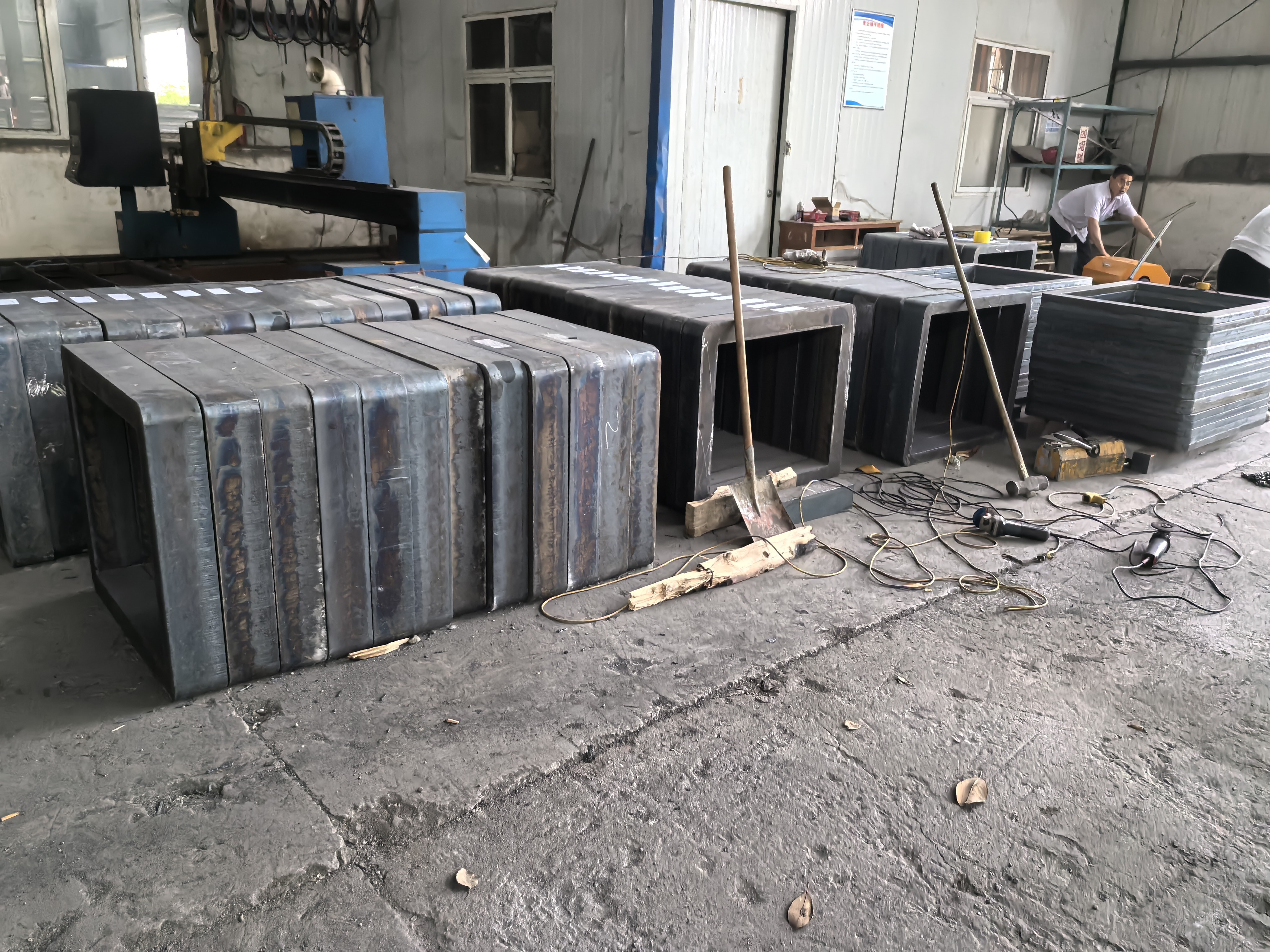
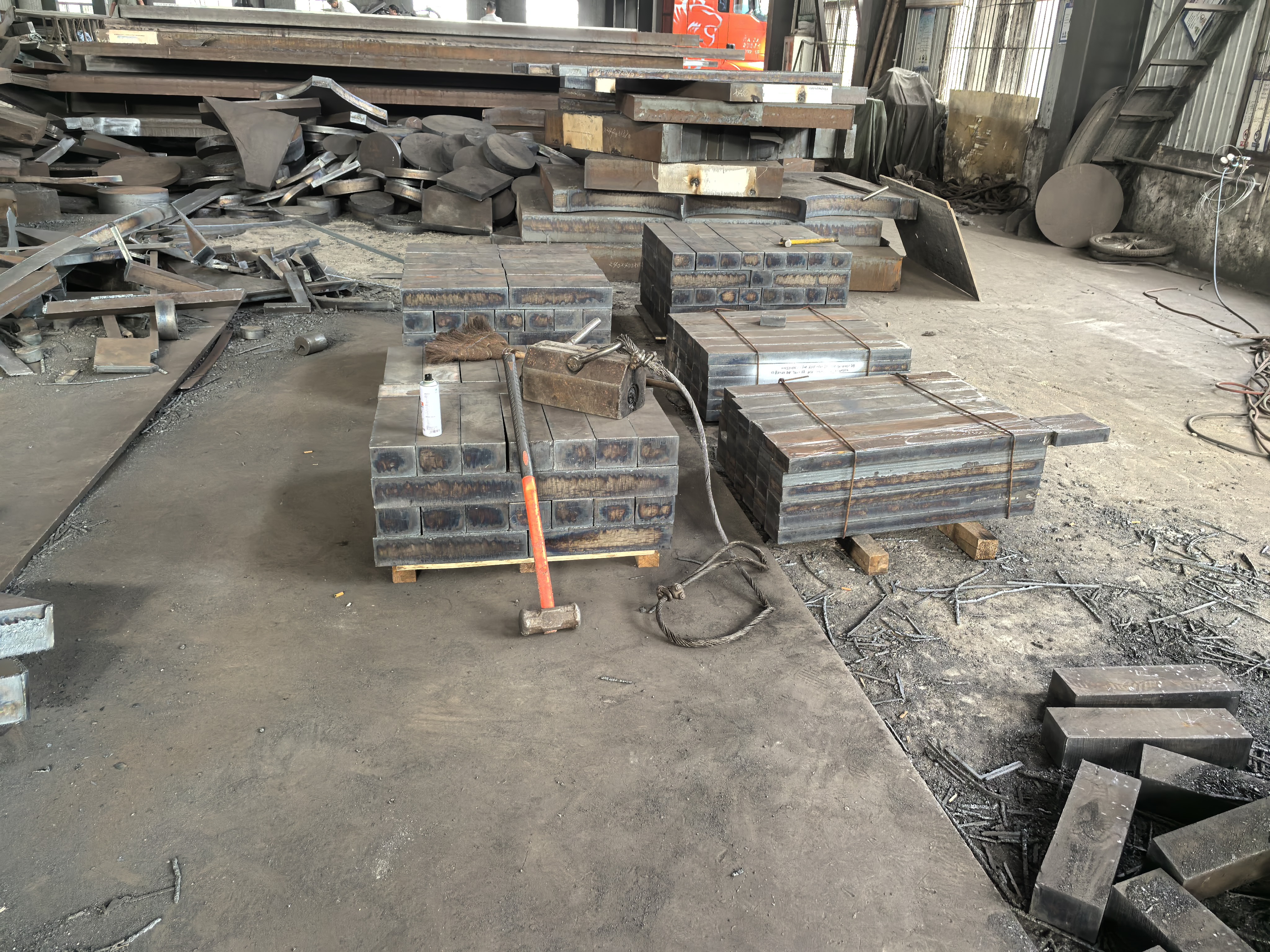
Typical agreements: flame contour ±2 mm, plasma ±1 mm, laser ±0.3–0.5 mm; rectangular parts check diagonals. After cutting, every part is dimension-checked and the heat number transferred onto the part — traceability travels with the profile. Bevel faces are de-slagged and primed; weld-prep surfaces go to ST2 before assembly.